
This tool does more than draw a room
Open Acoustic Planner in a desktop or notebook browser. You can build a room and study how sound may change inside it. The project can include the room shape, surface materials, doors, windows, furniture, acoustic treatment, loudspeakers, and listening positions.
The tool uses one clear workflow.
- You create the room shape.
- You choose materials for the walls, floor, and ceiling.
- You add furniture and acoustic treatment.
- You place the playback system and the listening or measurement positions.
- You study direct sound, early reflections, room decay, and room modes.
- You compare different conditions. You can then listen to the estimated difference with your own audio.
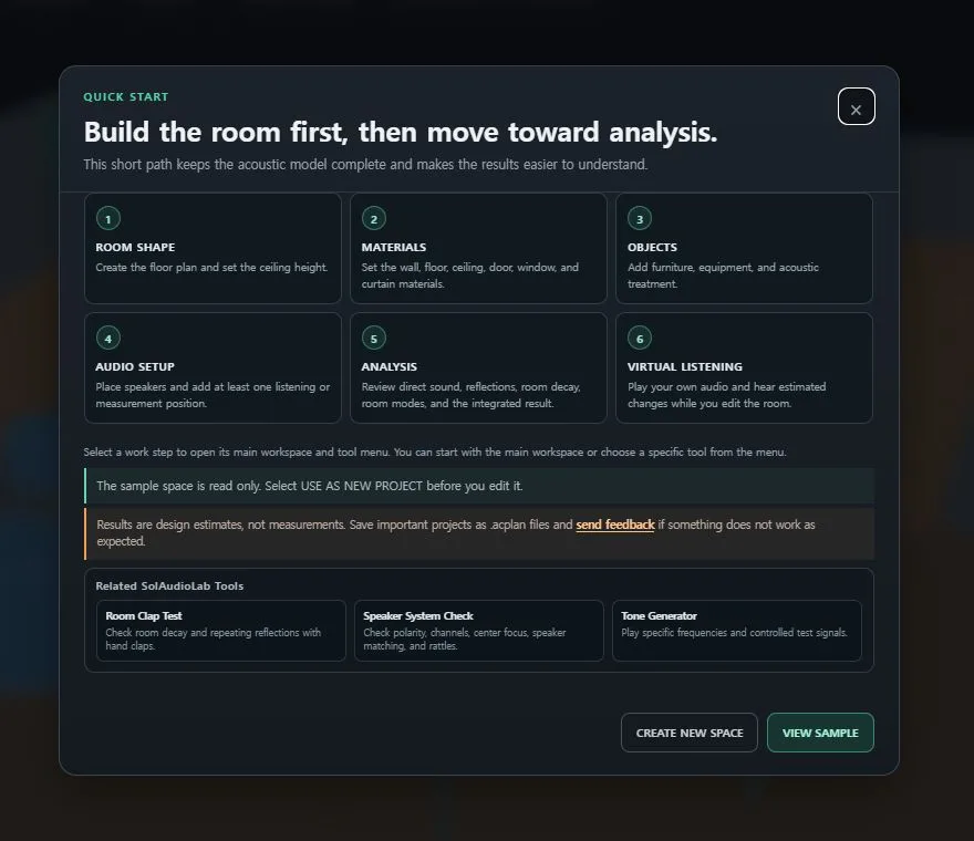
You do not need to learn every control before you start. The five large controls at the top follow the same order as the work. Each control opens the detailed tools for that step.
1. You can build more than a rectangular room
You can start with a rectangle, a room with a slanted wall, a trapezoid, an L-shaped room, or a room with a recessed area. You can also rotate the starting shape before you create it.
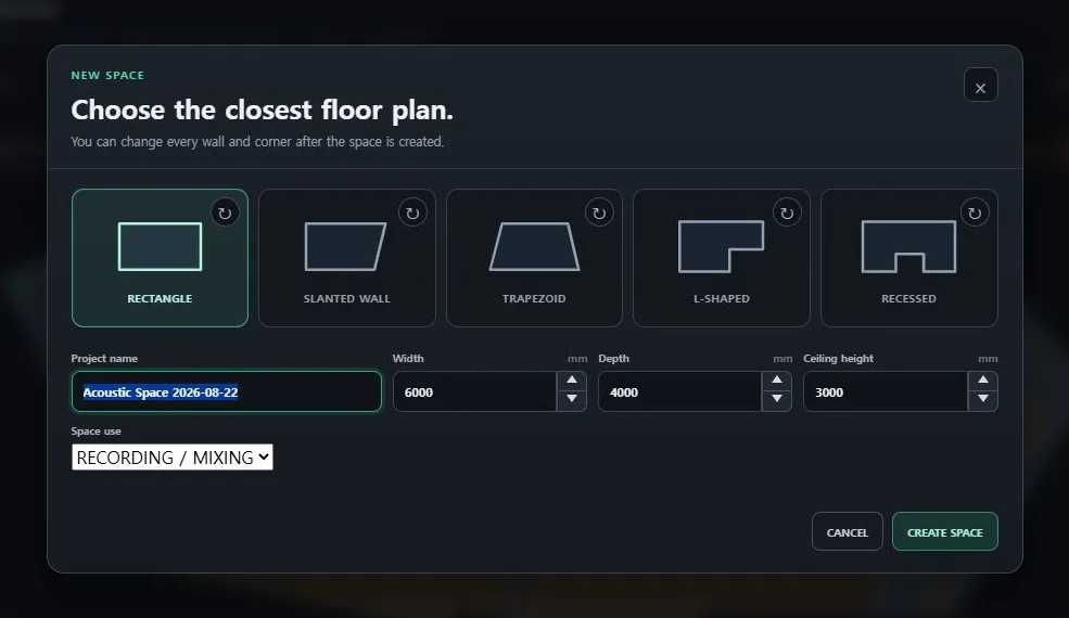
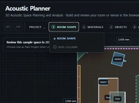
After you create the room, you can drag a corner or move a wall in a parallel direction. You can enter an exact wall length and angle. You can add or remove a corner. You can also make a corner square or replace it with a diagonal wall.
The model also supports full-height structural columns. A column can remain independent. A column near the boundary can also become part of the room outline. One Undo action restores the earlier shape.
This is useful because many real rooms are not simple boxes. You can test a floor plan that is closer to the space that you actually use.
2. Surface materials and wall features affect the model
The MATERIALS step lets you choose the whole wall group, one wall, the floor, or the ceiling. The presets include painted wall, concrete, brick, wood panel, glass, carpet, tile, stone, and acoustic ceiling tile.

Each preset includes estimated acoustic properties for six octave bands from 125 Hz through 4 kHz. The model separates absorbed energy, reflected energy, specular reflection, and diffuse reflection. These values are useful starting points. They are not certified data for a specific product. Real results can change with thickness, mounting, construction, and the air gap behind a material.
You can add a door, a window, a wall acoustic panel, or a curtain to a selected wall.


The wall front editor gives you a direct view of the selected wall. You can drag a feature into position. You can also enter exact dimensions in millimeters. A door has its own material. A window has a glass type. A wall acoustic panel has a thickness. A curtain has a weight, an air gap, and an open or closed state.
An open curtain uses its folded shape in the 2D and 3D views. The acoustic model then uses the exposed surface behind it. This makes an open and closed curtain a practical comparison condition.
3. Furniture can block and reflect sound paths
The OBJECTS step includes a sofa, a desk, a table, a cabinet, a bed, a bookshelf, and other simple items. You can change the size, position, and rotation. You can also create a simple custom block when the list does not include the item that you need.
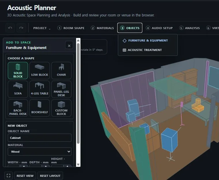
Furniture is not only visual decoration. The direct sound check can detect when a modeled furniture body blocks the route. Virtual Listening excludes a blocked direct route. Exposed furniture faces can also create first-order reflection paths.
This means that a desk, a sofa, or a bookshelf can change the result. You can move one item and immediately check which paths have changed.
The acoustic treatment tools include bass traps, diffusers, and ceiling clouds. A wall item keeps its wall connection when you edit the room. A corner bass trap can stay connected to two walls. A ceiling cloud keeps its ceiling gap when the room height changes.
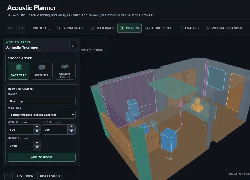
You can test each item separately. Turn one item off in the comparison. Change the size of a corner bass trap. Change the area or height of a ceiling cloud. Keep the same analysis position while you compare the results.
4. Loudspeaker direction and listening height are part of the project
The playback system can use a studio monitor, a public address loudspeaker, a stage monitor, a subwoofer, a floorstanding loudspeaker, or a wall or ceiling loudspeaker. You can add one item or create a left and right pair. You can edit the position, height, horizontal direction, and vertical tilt.
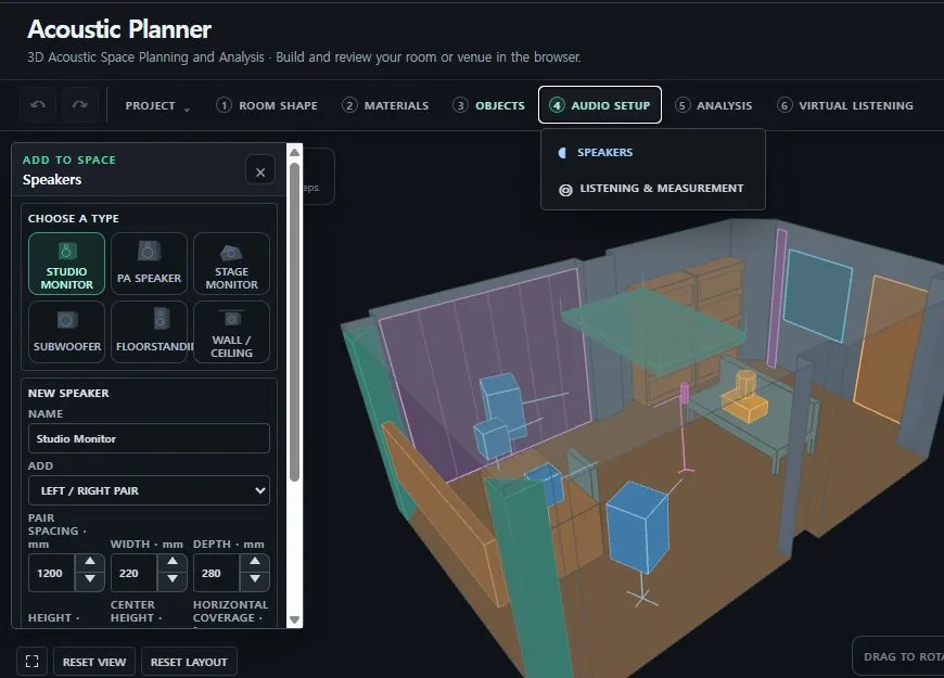
The acoustic source starts at the center of the front baffle. The direction line in the plan uses the same axis as the analysis engine. The three-dimensional cabinet and the stored direction data also use this reference.
The listening marker uses the height between the listener's ears. The measurement marker uses the microphone capsule height. You can create several positions and select the one that the analysis should use.
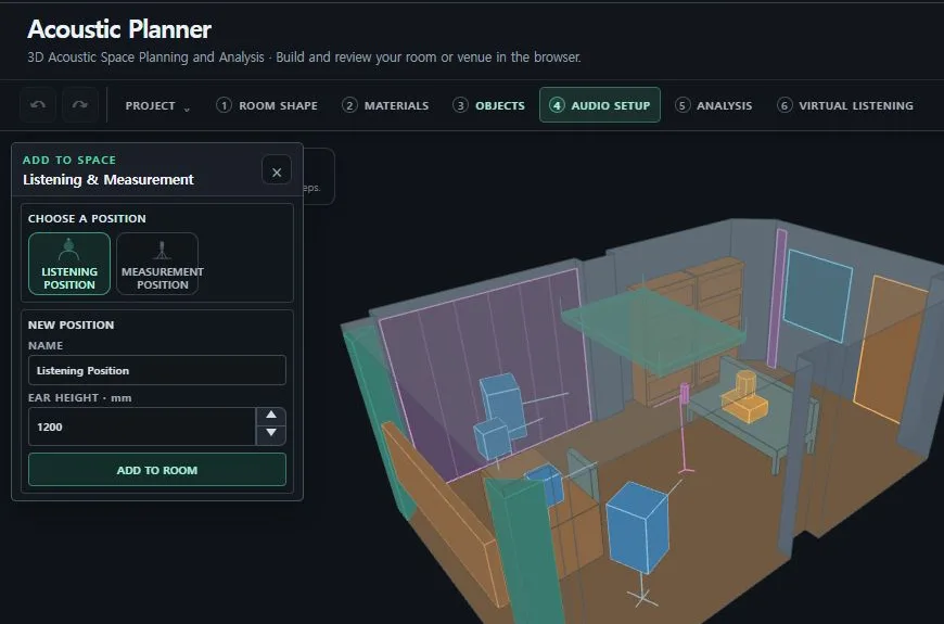
You can review the finished space in both views.

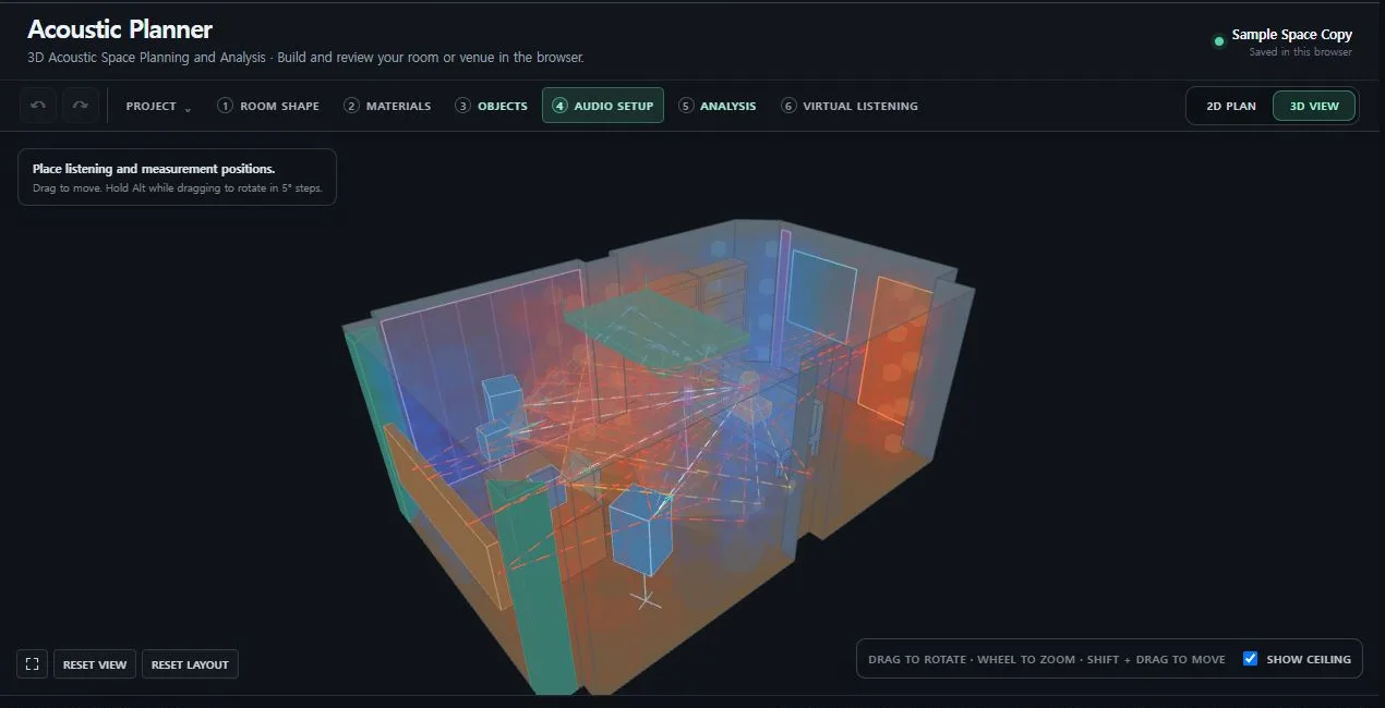
The 2D plan makes distances and directions easy to read. The 3D view makes height, obstruction, and surface attachments easier to understand. You can select and move objects directly. You can also hold Alt while you drag to rotate a movable item.
5. The analysis uses several views instead of one score
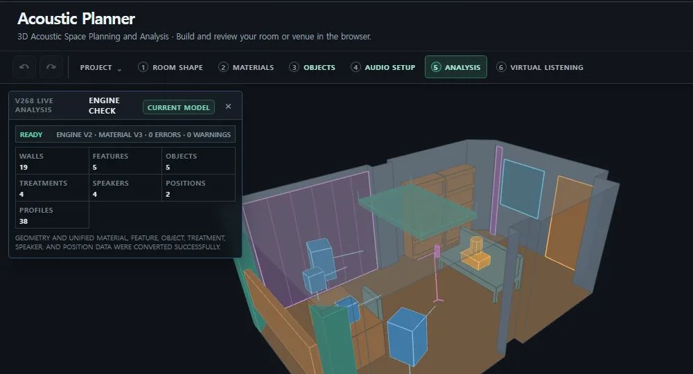
Run ENGINE CHECK before you study a project. It reports whether the editable room has become a valid calculation model. It also reports the converted walls, features, objects, acoustic treatment items, sources, and receivers.
Direct Sound shows the shortest path first
The direct sound engine calculates the route from the front baffle of each selected source to the selected receiver. It reports the travel time at 343 meters per second. It also reports the distance level relative to 1 meter and the angle between the loudspeaker axis and the receiver.
The result compares arrival times from the left and right sides. It also identifies a direct route that is blocked by modeled furniture.

Move the listening position a small distance to the left or right. Then change the loudspeaker spacing or toe-in angle. This simple test shows how quickly the arrival difference and axis angle can change.
Early Reflections identify the surface and arrival time
The early reflection engine finds valid first-order image-source paths. A path can reflect from a wall, the floor, the ceiling, a furniture face, or an acoustic treatment surface. The result uses the active material at the reflection point.
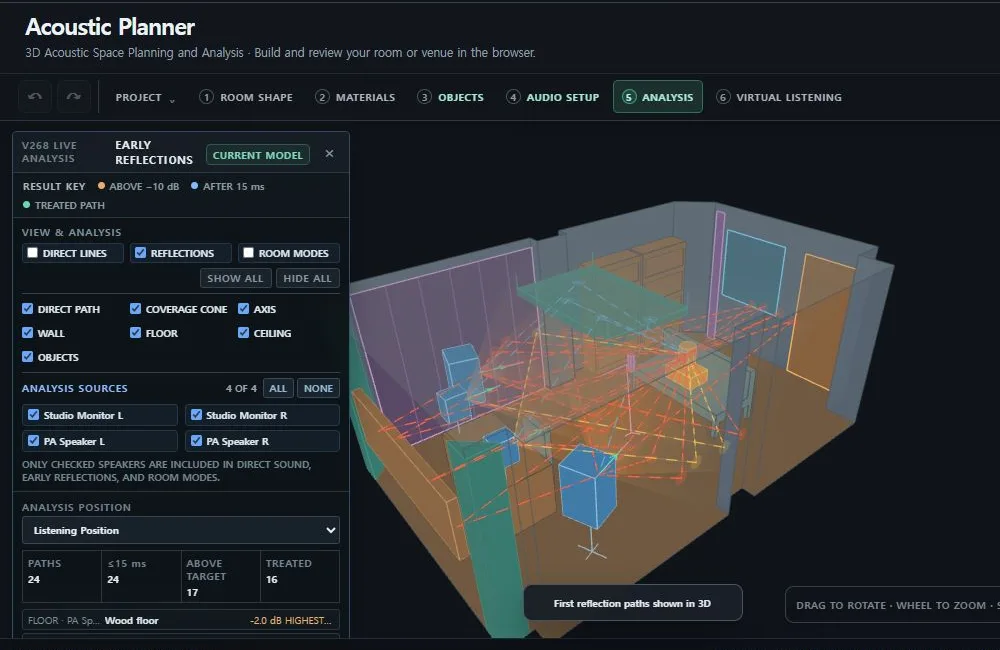
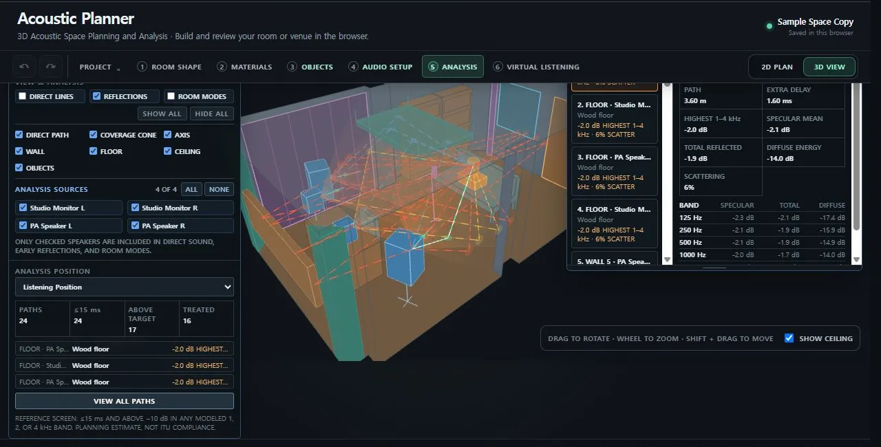
The path detail separates specular and diffuse energy. It also shows the modeled level in each octave band from 125 Hz through 4 kHz. You can select one route and see the exact reflection point in the 2D and 3D views.
This gives you a direct test. Find a strong early route. Add a wall acoustic panel or close a curtain near that point. The panel refreshes while you edit the room.
Room Decay shows six frequency bands
The room decay engine uses room volume and visible surface area. It also includes columns, simple room objects, air attenuation, materials, and installed acoustic treatment. The result covers 125 Hz, 250 Hz, 500 Hz, 1 kHz, 2 kHz, and 4 kHz.
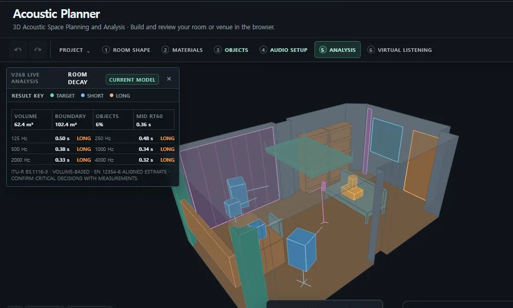
The graph compares the calculated values with the target for the selected use. This is more useful than one average reverberation value. You can see which bands move toward the target and which bands may become too short.
The decay calculation does not need a selected loudspeaker. You can still compare room finishes and acoustic treatment when every source is off.
Room Modes show where low-frequency problems occur
The room mode engine studies frequencies from 20 Hz through 200 Hz. It lists important modes and shows their spatial pattern. A rectangular room uses rigid-boundary three-dimensional eigenfrequencies. A non-rectangular floor plan uses an approximate grid eigenproblem without changing the original project geometry.

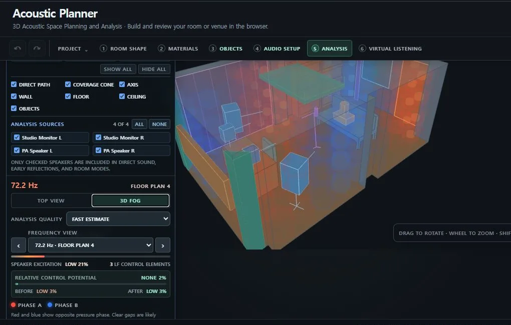
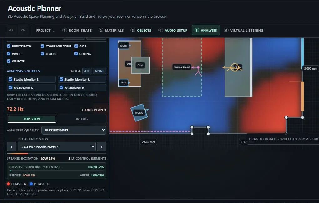
The OVERALL view highlights areas that remain strong across several important modes. An individual frequency uses red and blue for opposite spatial phase. Areas near an estimated node remain clear.
Moving a source does not move the standing-wave pattern of the room. It changes how strongly that source excites the pattern. It also changes the effect at the selected listening or measurement position.
6. You can compare the current room with another condition
ROOM ACOUSTIC COMPARISON places the current room and a temporary comparison in one workspace. You can include or exclude each acoustic treatment item. You can also choose temporary wall, floor, and ceiling finishes. The selected sources and receiver stay visible in the same window.
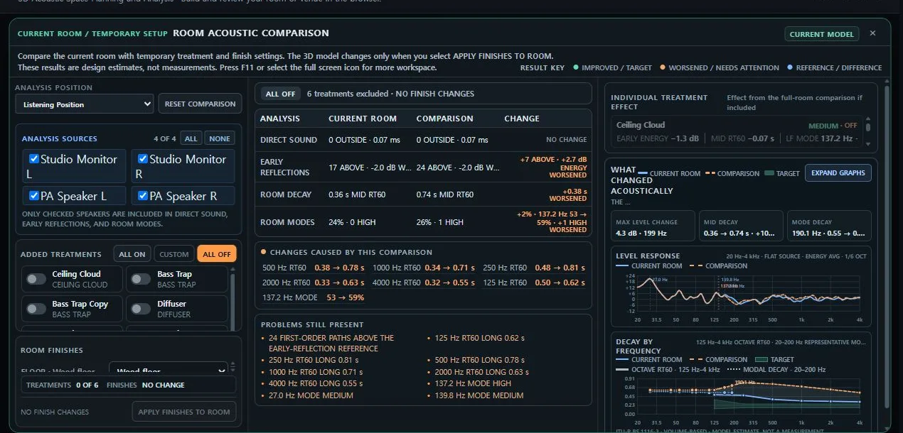
Each treatment card removes only that item and runs the same room calculations again. You can see how one item changes early reflection energy, the middle-frequency decay time, and an important low-frequency mode.
Temporary finishes do not change the project until you choose APPLY FINISHES TO ROOM. The treatment switches remain comparison controls. They do not remove items from the project.
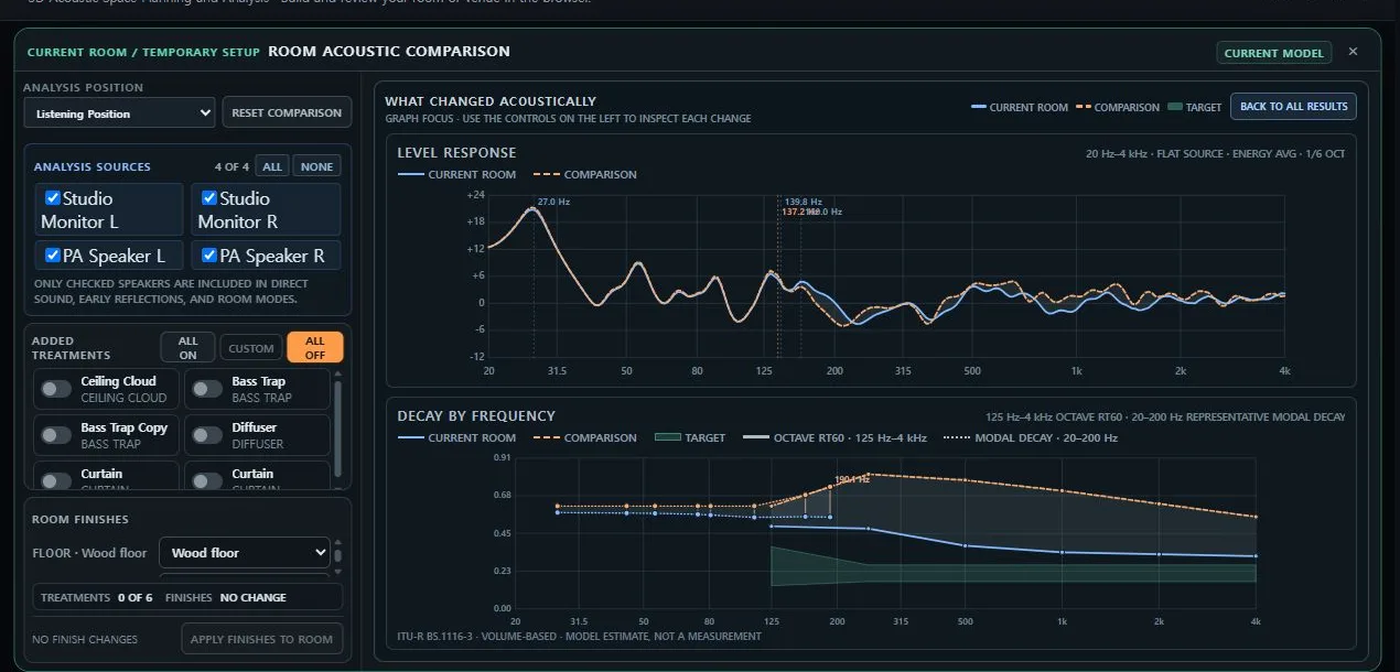
The level graph covers 20 Hz through 4 kHz. Both curves use the same reference. The low-frequency region uses damped room modes. The higher region uses direct sound and calculated first-order reflections. The decay graph keeps low-frequency modal decay separate from the six statistical room-decay values.
This result is not a microphone measurement. It is not a certified frequency-response prediction. Use it to compare the direction and size of a modeled change in the same project.
7. These tests are useful when you start
- Move the listening position forward or backward by 20 or 30 centimeters. Keep every other condition unchanged.
- Change the spacing between the left and right loudspeakers. Test the toe-in angle separately.
- Exclude one ceiling cloud, diffuser, or bass trap. Check the individual effect before you change another item.
- Compare carpet, wood, and concrete as temporary finishes. Check the decay graph before you apply a finish to the project.
- Select one source pair at a time. Compare the same receiver with the studio monitor pair and the public address pair.
- Move a desk or cabinet. Check whether the direct route or a furniture reflection changes.
- Compare a rectangular room with an L-shaped room. Review the different room mode methods and their limits.
Change only one condition during each test. Keep the same sources and receiver. This makes the reason for each change easier to understand.
8. The engines use established acoustic models with clear limits
Acoustic Planner does not create one universal room score. Each engine answers a different question. The comparison workspace combines the results without hiding their different limits.
- Direct Sound V1 uses three-dimensional distance, travel time, distance loss, loudspeaker axis angle, arrival difference, and simplified furniture obstruction.
- Early Reflections V4 uses first-order image-source paths and six-band material properties. The geometric basis follows the same family of methods as the classic Allen and Berkley image-source paper.
- Room Decay V3 separates room boundaries, objects, air attenuation, and equivalent absorption area. Its structure follows the enclosed-space absorption and reverberation-time model in BS EN 12354-6.
- The Recording and Mixing target uses the volume-based nominal reverberation time from ITU-R BS.1116-3. The early reflection screen also follows its time-based and frequency-specific structure. The tool does not claim compliance with the recommendation.
- Room Modes V7 uses exact three-dimensional rigid-boundary eigenfrequencies for a rectangular room. It uses an approximate finite-difference grid eigenproblem for a non-rectangular floor plan.
- Listening Response V2 uses a damped eigenmode sum at low frequencies. It uses the complex sum of direct sound and first-order specular reflections above the modal region. It adds diffuse energy separately and joins the two regions near the reliable modal limit.
- Virtual Listening V2 builds a stereo impulse response from the direct routes and as many as 32 strong valid first reflections. It also adds a diffuse late tail that follows the six room-decay bands. Real-time browser playback uses the audio graph and convolution capabilities described by the W3C Web Audio API.
The current model does not include the measured frequency response or phase of a specific loudspeaker. It does not include detailed frequency-dependent directivity, diffraction, higher-order reflections, construction-specific wall impedance, or a full three-dimensional wave solver. Virtual Listening does not include an individual head-related transfer function. Material presets are not certified product measurements.
Use the results to plan and compare. Confirm important construction and installation decisions with measurements in the real room.
9. You can save projects in three different ways
The browser can save the current project automatically. You can also export an .acplan file and open it on another compatible computer.

A signed-in user can save a private project in MY SOLAUDIOLAB. The user can then open the project on another signed-in desktop or notebook computer. Browser projects and cloud projects remain separate. Deleting a cloud copy does not delete the browser copy.
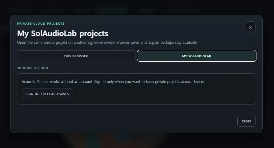
The cloud item contains the normalized room project. It can include geometry, materials, furniture, acoustic treatment, sources, receivers, and analysis settings.
Virtual Listening audio stays in the browser. The uploaded audio data, local filename, decoded samples, playback state, and listening snapshots are not part of a cloud project.
10. The final reward is Virtual Listening
The visual analysis explains why a condition changes. Virtual Listening lets you hear an estimate of that change with your own audio.
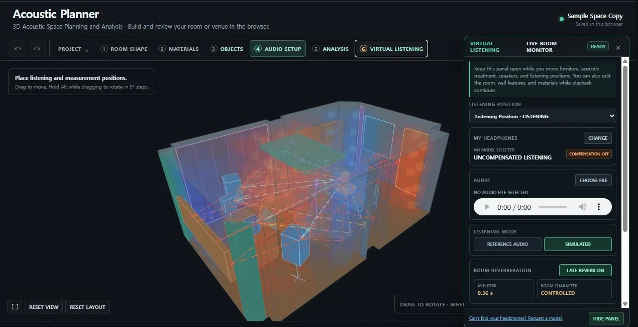
Load an audio file and switch between ORIGINAL AUDIO and SIMULATED. The simulated mode uses the selected sources and receiver. It combines direct routes, valid first reflections, and the estimated late decay.
You can continue to edit the room while the audio plays. Move a loudspeaker, a receiver, a furniture item, or an acoustic treatment item. The tool rebuilds the response and uses a short crossfade to move to the new result.
You can select a headphone model. When a verified profile is available, the tool can apply a limited inverse compensation. An unlisted model can remain uncompensated. You can still hear the relative room change.

Use SAVE A and SAVE B to keep two calculation snapshots. For example, save the current layout as A. Move the playback system forward and add a ceiling cloud. Save that condition as B. You can then switch between the two estimates during the same section of music.
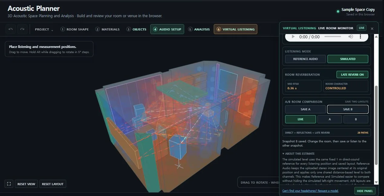
Virtual Listening is not a measured binaural capture of the real room. It is a browser-based comparison model. It helps you hear the relative effect of changes to direct sound, first reflections, and statistical late decay.
You can build the room, inspect the paths, locate low-frequency problem areas, compare conditions, and listen to the estimated change. All of these steps stay inside one browser project.